

Please ensure Javascript is enabled for purposes of website accessibility

7 Tips for Choosing the Right Vent Relief Valve

Selecting the right Vent Relief Valve is a pressure-management decision, not a routine purchasing task. In the field, small errors can become serious quickly. A tank may breathe during filling, emptying, heating, or sudden cooling. Each condition changes the required flow capacity. API Standard 2000, Venting Atmospheric and Low-Pressure Storage Tanks, remains a key industry reference for these calculations. It addresses normal and emergency venting, sizing principles, and installation considerations.

Real incidents show why careful selection matters. U.S. Chemical Safety Board investigation reports repeatedly identify inadequate hazard analysis, poor equipment design, and weak operating controls as contributing factors in process incidents. OSHA’s Process Safety Management materials also emphasize accurate equipment information, documented procedures, and management of change. These lessons apply beyond large refineries. A small chemical tank, a food-processing vessel, or a solvent drum can still experience damaging pressure changes.

Fit is not enough.

This guide presents seven practical tips for choosing a Vent Relief Valve with greater confidence. We will examine set pressure, relieving capacity, temperature, fluid compatibility, connection size, discharge routing, and inspection needs. Materials matter. Stainless steel may resist one chemical but fail in another service. A valve that performs well in a clean-water application may stick when exposed to vapors, crystals, or polymerizing fluids. That assumption fails. Review the process data, confirm the governing standard, and involve a qualified engineer before approval. The recommendations draw on API 2000, NFPA 30, CCPS process-safety guidance, and documented industry incident experience. Some applications still require deeper analysis. That is worth acknowledging.
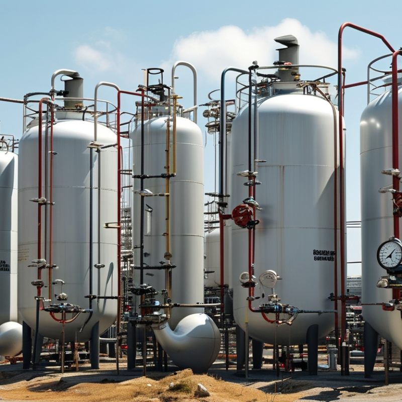
7 Tips for Choosing the Right Vent Relief Valve

Understand the Purpose and Function of a Vent Relief Valve

A vent relief valve protects tanks and process vessels from pressure and vacuum damage. It opens when internal pressure exceeds a set point, then closes when conditions return to a safe range. Vacuum protection works in the opposite direction. This function matters during filling, draining, heating, cooling, and sudden shutdowns. API Standard 2000 identifies these operating events as key sizing conditions. The standard also requires attention to normal and emergency venting. A valve is not merely a pipe fitting.

Tip 1: Define the hazard first. Check the stored liquid, vapor pressure, temperature, and possible chemical reaction.

Tip 2: Calculate both pressure and vacuum loads. Many failures begin with ignored vacuum conditions.

Tip 3: Match the set pressure with the vessel’s maximum allowable working pressure. OSHA’s Process Safety Management rule includes 14 management elements, showing why relief selection must connect with procedures, training, and maintenance.

Tip 4: Confirm the required flow capacity from credible process data, not guesswork. Small errors become expensive.

Tip 5: Consider weather, dust, corrosion, and freezing at the outlet.

Tip 6: Review inspection access before installation. A technically correct valve can become impractical in a crowded plant.

Tip 7: Document assumptions, calculations, and test results. API Standard 2000 and recognized pressure-vessel codes provide useful design references, but site conditions still control the final decision. I have seen specifications focus heavily on pressure and overlook cleaning frequency. That gap deserves another review. Select materials for the real service, not the catalog description.

Evaluate Pressure, Temperature, and Flow Requirements

7 Tips for Choosing the Right Vent Relief Valve

Tip 1 Confirm the vessel’s normal operating pressure and maximum allowable working pressure. A valve set too low may vent unnecessarily. A valve set too high may protect nothing.

Tip 2 Account for pressure spikes during filling, heating, cleaning, and blocked vent conditions. Review real operating records, not only design assumptions.

Tip 3 Select materials that tolerate the process fluid and its concentration. Corrosion can change valve performance quietly.

Tip 4 Check the complete temperature range, including startup and shutdown. Temperature affects spring behavior, seals, and discharge capacity.

Tip 5 Compare the valve’s rated flow with the largest credible release scenario. Estimate gas, vapor, or liquid flow carefully.

Tip 6 Examine inlet and outlet piping losses. A narrow pipe, long run, or sharp elbow can reduce effective relief performance. Keep the path short where practical.

Tip 7 Consider back pressure from downstream equipment. Constant and built-up back pressure can alter the valve’s opening point.

In field reviews, I have found that flow calculations are often treated as fixed facts. They are not. Process conditions change, and old data may be incomplete. Verify pressure gauges, temperature sensors, and maintenance records before final selection. Test the valve under controlled procedures, then document the results. An experienced engineer should review the sizing basis, material compatibility, and installation details. Small oversights matter.

Select the Appropriate Valve Type and Materials

Choosing the correct vent relief valve begins with understanding the vessel, not the valve catalog. Identify the required relieving pressure, operating temperature, fluid state, and expected flow rate. A valve sized only by pipe diameter may fail during a rapid pressure rise. Check the connection.

Select the valve type according to the duty. Spring-loaded valves suit many standard pressure vessels and respond quickly to overpressure. Pilot-operated valves can handle larger systems, but they need cleaner control lines and closer maintenance. Vacuum relief may also be necessary when a tank cools or drains rapidly. In field reviews, engineers often find that thermal expansion was overlooked. That small gap in analysis can create a serious hazard.

Material selection should match the process fluid and surrounding environment. Stainless steel may resist moisture and mild chemicals, while special alloys may be needed for aggressive media. Confirm gasket compatibility at the lowest and highest operating temperatures. Consider outdoor exposure, salt air, dust, and repeated cycling. Check the connection. Review certification documents, test records, and the manufacturer’s pressure-temperature data before approval. A qualified engineer should verify the final selection against applicable pressure equipment requirements. Do not rely on habit. Even an experienced team can miss condensation, corrosion under insulation, or a blocked vent path. Leave a practical safety margin, but avoid excessive settings that reduce system protection.

Check Compatibility, Standards, and Installation Conditions

7 Tips for Choosing the Right Vent Relief Valve

Compatibility comes before capacity. Confirm the vessel’s fluid, temperature, pressure, and vapor composition. Check wetted materials against corrosion data, not assumptions. A valve suitable for water may fail quickly with solvents or acidic vapors. Verify connection size and pressure class against the tank nozzle. Then compare certified flow capacity with the required venting rate. API Standard 2000 provides guidance for normal and emergency venting of atmospheric and low-pressure storage tanks. Its calculations consider liquid movement, thermal breathing, and fire exposure.

Standards matter, but installation details decide performance. Check whether the design follows API 2000, ISO 28300, or applicable local pressure equipment rules. NFPA 30 also addresses flammable and combustible liquid storage conditions. Keep the vent line short, supported, and free from liquid traps. A sagging pipe can collect condensate and obstruct the valve. Install the device upright unless the manufacturer’s instructions permit another position. Protect discharge outlets from rain, insects, paint, and ice. Confirm that nearby equipment will not create backpressure. The U.S. Chemical Safety Board has repeatedly linked poor relief-system design and maintenance to serious process incidents.

Ask for calibration records, material certificates, and test evidence. Inspect the seat and spring area during commissioning. Record the set pressure beside the vessel. That small label helps during a hurried inspection. I have seen teams select a valve from diameter alone; that shortcut is convenient, but incomplete. Recheck assumptions after production changes, because a new solvent, filling rate, or cleaning method can alter venting demand. Get a qualified engineer to review the final arrangement.

7 Tips for Choosing the Right Vent Relief Valve - Check Compatibility, Standards, and Installation Conditions
No. Selection Tip What to Check Practical Guidance Typical Acceptance Criteria Priority
1 Define the Required Pressure or Vacuum Set Point Confirm the vessel design pressure, allowable vacuum, normal operating pressure, temperature range, and the pressure or vacuum level that must initiate relief. Select a valve set point below the protected equipment's maximum allowable working pressure for pressure relief. For vacuum protection, ensure the valve opens before the vessel reaches its allowable external-pressure limit. Set pressure is compatible with the vessel rating and operating envelope; no nuisance opening is expected during normal operation. Critical
2 Match the Valve to the Process Fluid Identify the gas, vapor, liquid, dust, corrosive constituents, toxicity, flammability, temperature, and potential for polymerization or crystallization. Use materials and sealing elements compatible with the fluid and temperature. Consider corrosion, embrittlement, swelling, deposits, and the possibility of hazardous discharge requiring a closed vent or recovery system. Wetted materials, gaskets, and elastomers are chemically and thermally compatible with the process throughout the service life. Critical
3 Size for the Maximum Credible Venting Load Calculate the required relieving capacity for credible scenarios such as filling or emptying, thermal expansion, gas blow-by, fire exposure, runaway reaction, or utility failure. Use the applicable engineering calculation method and the valve manufacturer's certified capacity data. Do not size only from the normal operating flow rate. Account for the relieving pressure, temperature, fluid properties, and backpressure. Certified valve capacity meets or exceeds the calculated required capacity with documented assumptions and an appropriate engineering margin. Critical
4 Verify Applicable Codes and Standards Determine which regulations and standards apply to the equipment, location, service, and relief device type. Review applicable pressure-vessel, relief-device, piping, hazardous-area, environmental, and workplace-safety requirements. Common references may include recognized pressure-relief and tank-venting standards, but the governing code depends on the installation jurisdiction and service. The selected valve has the required certification, markings, test records, materials documentation, and inspection status for the installation. Critical
5 Check Connection Size, Pressure Class, and Backpressure Compare nozzle size, connection type, flange or thread rating, inlet pressure loss, outlet pressure, and any built-up or superimposed backpressure. Keep inlet and outlet piping arranged to avoid excessive pressure loss, liquid pockets, vibration, and unsupported loads. Verify that backpressure will not reduce capacity or prevent the valve from reseating correctly. Piping ratings exceed the design conditions; calculated pressure losses and backpressure remain within the valve's approved operating limits. High
6 Evaluate the Installation Environment Assess outdoor exposure, ambient temperature, rain, snow, dust, salt spray, vibration, elevation, accessibility, and hazardous-area classification. Provide weather protection or insulation where required, while keeping the discharge path unobstructed. Install the device upright when specified and provide safe access for inspection, testing, and maintenance. The valve is protected from freezing, fouling, impact, and unauthorized adjustment, with clear access and safe discharge routing. High
7 Plan Testing, Maintenance, and Documentation Confirm inspection intervals, set-pressure testing, cleaning requirements, spare parts, calibration control, tamper protection, and replacement procedures. Maintain installation drawings, sizing calculations, material certificates, test certificates, operating instructions, and inspection records. Establish a documented schedule based on service severity and regulatory requirements. The valve can be isolated, tested, serviced, and returned to operation without compromising protection or violating the governing safety requirements. High

Compare Maintenance Needs, Safety Features, and Total Cost

Choosing the right vent relief valve requires more than comparing purchase prices. Maintenance needs, safety features, and total cost should guide the decision.

Tip 1: Check maintenance access. A valve with removable internal parts can reduce service time. Ask how often inspection is recommended, and whether seals are easy to replace. In field work, cramped access often creates hidden labor costs. That detail is easy to miss.

Tip 2: Compare safety features carefully. Confirm the valve matches the vessel’s pressure, temperature, and operating medium. Look for stable set pressure, corrosion-resistant materials, clear discharge direction, and protection against accidental adjustment. A qualified engineer should verify sizing and installation against applicable codes. Never rely only on a supplier’s chart. Real operating conditions can differ from the original design assumptions.

Tip 3: Calculate total cost over its working life. Include purchase price, installation, testing, spare parts, downtime, and disposal. A cheaper valve may require frequent cleaning or earlier replacement. A more durable option may cost less after several inspection cycles. Request service records when possible. They reveal practical performance better than polished product claims.

Keep records. Simple records help.

One caution remains: maintenance intervals are not universal. Dust, vibration, moisture, and pressure fluctuations can change them. Review the schedule after the first operating period, and adjust it with documented technical evidence. A small mistake in estimation can become expensive, so leave room for reassessment.

Article Source: