

What Is an Industrial Air Compressor and How Does It Work?
Industrial Air Compressor systems quietly power many factories, workshops, and processing lines. They convert mechanical energy into pressurized air for tools, controls, cleaning, and automation. Unlike a household pump, an industrial unit must deliver stable flow for long operating hours. Its performance affects production speed, product quality, and energy costs.
A motor drives a compression element, such as a rotary screw or reciprocating piston. Air enters through an intake filter, where dust and moisture can begin causing trouble. The element compresses the air, raising its pressure and temperature. A cooler then removes heat before the receiver stores compressed air for demand changes. Dryers, filters, valves, and controllers complete the system. Small parts matter.
In daily maintenance, technicians check oil condition, leaks, drain traps, vibration, and discharge temperature. A faint hiss near a fitting may represent significant wasted energy over a full shift. Manufacturer data, pressure requirements, duty cycles, and local safety rules should guide equipment selection. Reliable explanations must connect theory with measurable field conditions, not merely repeat specifications.
This guide examines how an Industrial Air Compressor works, how major designs differ, and where efficiency is often lost. It also considers installation, maintenance, noise, and safe operation. The explanation remains practical, but it is not perfect. Real systems vary with climate, load patterns, and neglected components. That limitation matters. A compressor can appear correctly sized while still struggling during peak demand. Careful measurement usually reveals the truth.
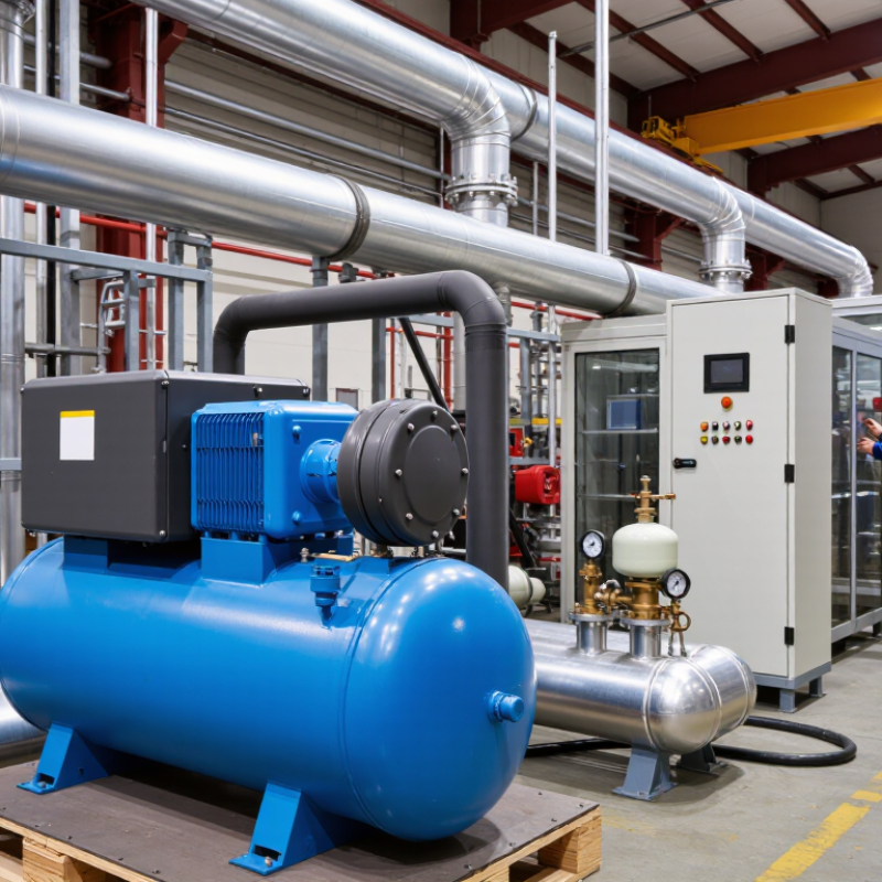
Industrial Air Compressor Definition: 7–10 bar Pressure for Factory Systems
What Is an Industrial Air Compressor and How Does It Work?
An industrial air compressor converts mechanical energy into pressurized air for factory systems. Many production lines operate between 7 and 10 bar. This range supports pneumatic tools, valves, cylinders, and automated handling equipment. The compressor draws air through an intake filter. A screw or piston mechanism then reduces its volume. Pressure rises as the air becomes more concentrated. The compressed air moves into a receiver tank before distribution.
A stable 7–10 bar supply requires more than a powerful compressor. The receiver absorbs sudden demand changes, such as several tools starting together. A refrigerated or desiccant dryer removes moisture from the air stream. Filters capture oil, dust, and pipe scale. Without treatment, water can damage valves and spoil painted surfaces. Pressure regulators should match each machine’s actual requirement. Excess pressure wastes electricity and may shorten component life.
Factory technicians should check pressure at the point of use, not only at the compressor outlet. A gauge may show 8 bar while a distant machine receives much less. Leaks around fittings are common and surprisingly expensive. Listen near joints during quiet periods. Maintenance records should include filter changes, drain checks, temperature readings, and unusual vibration. One detail is often missed: a compressor sized for average demand may struggle during peak shifts. Adding capacity can help, but improving storage and repairing leaks may be the wiser first step.
What Is an Industrial Air Compressor and How Does It Work? - Industrial Air Compressor Definition: 7–10 bar Pressure for Factory Systems
| Data Dimension | Typical Industrial Value or Description | How It Works or Why It Matters |
|---|---|---|
| Basic definition | An industrial air compressor is a machine that converts mechanical energy into compressed-air energy for factory equipment and processes. | The compressor draws in atmospheric air, reduces its volume, and raises its pressure before delivering it to a receiver or distribution system. |
| Common factory operating pressure | 7–10 bar(g), approximately 100–145 psi(g) | This range is widely used for pneumatic tools, automation equipment, assembly lines, packaging machinery, and general plant air systems. |
| Pressure terminology | Pressure is commonly specified as bar(g) or psi(g); atmospheric pressure is about 1.013 bar absolute at sea level. | Gauge pressure excludes atmospheric pressure, while absolute pressure includes it. Correct terminology prevents sizing and control errors. |
| Main compression stages | Intake, compression, cooling, moisture separation, storage, and distribution | Air passes through an intake filter, compression element, aftercooler, separator, receiver, dryer, and point-of-use filtration as required. |
| Common compressor technologies | Rotary screw, reciprocating piston, centrifugal, and rotary vane | Rotary screw machines suit continuous factory demand; piston compressors suit intermittent or smaller loads; centrifugal units suit large, steady flows. |
| Drive configuration | Fixed-speed or variable-speed electric motor drive | Fixed-speed units are effective near a steady load. Variable-speed drives adjust motor speed to better match changing air demand and may reduce unloaded running. |
| Typical flow measurement | m³/min, m³/h, or cubic feet per minute (cfm) | Required flow should be based on the combined demand of connected equipment, expected duty cycle, leakage, and a controlled design margin. |
| Compressed-air quality | Ranges from general-purpose plant air to dry, oil-controlled air for critical processes | Filters, dryers, drains, and suitable compressor construction are selected according to allowable particles, water, oil, and microbial contamination. |
| Air treatment equipment | Aftercooler, water separator, refrigerated or desiccant dryer, coalescing filter, and particulate filter | Treatment removes heat, condensed water, oil aerosols, and particles that could damage tools, products, valves, or control systems. |
| Air receiver function | A pressurized storage vessel installed downstream of the compressor | The receiver dampens pressure fluctuations, supports short demand peaks, helps remove condensate, and reduces frequent compressor cycling. |
| Factory applications | Pneumatic tools, actuator control, material handling, cleaning, packaging, instrumentation, and process air | Compressed air provides a controllable, distributed power source where electric or hydraulic systems may be unsuitable. |
| Energy consumption | Often the largest operating cost over the equipment life cycle | Pressure set points, leakage, intake restriction, poor maintenance, artificial demand, and unloaded operation can significantly increase energy use. |
| Heat generation | A large portion of the motor input energy becomes heat during compression | Cooling systems remove heat from the compressed air and compressor package. In some facilities, recovered heat can support water or space heating. |
| Routine maintenance | Inspect filters, oil level or separator, belts, drains, coolers, hoses, safety devices, and system leaks | Preventive maintenance preserves flow and pressure, protects the compression element, improves reliability, and helps maintain air quality. |
| System design principle | Size the system for actual peak and average demand rather than compressor capacity alone. | A complete design considers pressure drop, pipe diameter, storage, duty cycle, redundancy, air quality, expansion plans, and operating conditions. |